(Aircraft Structural Integrity Program)
=>
Home
Overview
The ASIP dates back to a
1950's Air Force publication on structural integrity requirements. It was known
from an early stage that ASIP was a vital program in prolonging the life and
ensuring the structural safety of all aircraft. Meetings began in the 1970's,
but it wasn't until 1984 that it was reshaped into the current conference
format. Incidents like the 1988 Aloha Flight 243 Air Disaster highlighted the
importance of ASIP requirements and the contributions of the ASIP community, to
preclude the recurrence of such tragedies in the future. The ASIP Conference helps
to accomplish this through the personal interactions of its attendees,
resulting in the exchange of vital ideas and technology.
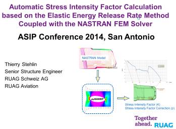
Stehlin Engineering Contribution to
ASIP Conference 2014
Mr Thierry Stehlin has been
selected to hold a presentation in name of RUAG during the ASIP
Conference 2014. The presentation shows an application of the use of the pyNASSIF tool to
perform CG analysis in a spar of the outer wing of the Swiss F/A-18 aircraft.
--------------------- Presentation
Abstract ---------------------
From 2003 to 2005, RUAG Aviation
performed a Full Scale Fatigue Test (FSFT) of the F/A-18 fighter aircraft in
order to validate the Swiss-specific structural modifications implemented
during the procurement phase of this aircraft.
The tear down inspection at the
end of the FSFT revealed a 16in long crack in the outer wing spar 3 in spanwise direction along the web to bottom flange interface
(about 1/4 of spar severed). The crack growth was not obvious to explain and no
standard model was applicable to such a case. The use of pyNASSIF
script combined with the R-Curve approach and AFGROW runs permitted to:
1. Understand the crack path and the
final cracks lengths found in the test article. Note that all crack growth (CG)
modes [I, II and III] were active at different stages of the CG and a method to
assess the crack path is shown.
2. Explain partial static failure
followed by subsequent crack growth found by quantitative fractography
(QF).
3. Develop a total life model for
fleet support.
The method permits to calculate
the stress intensity factor (K) of up to 2 thru cracks fronts in virtually any
thin structures. It automatically accounts for load redistribution between the
parts and non-linear behaviour can also be taken into account if required. The
cracks are implemented in a NASTRAN FEM model by unzipping the nodes along the
crack path.
The process of running the model
at several cracks sizes and extracting the necessary information (cracks
lengths, crack increments, material properties, plate thickness and
elastic-energy) to calculate the stress intensity is automatized in pyNASSIF, which main output is K in function of the crack
length. In cases of two crack fronts the output is a set of two K matrices, one
for each crack tip, with dependence on tip 1 and tip 2 lengths. K solutions can
then be imported into a standard software to perform CG calculations.
Content:
Ø
Introduction
to RUAG Aviation.
Ø
Introduction
to the Swiss F/A-18 Full Scale Fatigue Test (FSFT).
Ø
Presentation
of one of the cracks discovered in the outer wing at the end of the FSFT.
Ø
Description
of pyNASSIF (theoretical background &
implementation).
Ø
Validation
of pyNASSIF by comparing the results for standard
solutions with other sources like NASGRO, AFGROW and FRANC2D.
Ø
Application
of pyNASSIF to F/A-18 outer wing spar 3 crack as part
of total life model development.
Ø
Comparison
of the analytical results with the FSFT findings (strain gages and QF
information).
Ø
Impact
on Swiss F/A-18 fleet management.
Conclusions
and significance:
Ø
A
new application of the elastic energy release rate concept is presented.
Ø
The
method is straightforward and powerful.
Ø
The
method is validated against other sources.
Ø
The
method can be used to solve very complex cases, such as the F/A-18 outer wing
spar crack.
Ø
The
method can be easily implemented by any company provided that a FEM solver is
available.
-----------------------------------------------------------------
|
|
Presentation |
|